

 Current position > News detail
『Vortex flowmeter』Related information(clamp on meter|electromagnetic meter|venturi meterrotameter|orifice meter|ultrasonic flow meter|mass flow meter|coriolis mass flow meter|coriolis flow meter|magnetic flow meter|magmeter flow meter|magflow flow meter|mag meter flow meter|electromagnetic flow meter|vortex flow meter|turbine flow meter|thermal mass flow meter|thermal flow meter|rotameter flow meter)
1. The menu unlock password for the Aoxin ASL-20 swirl vortex flowmeter is 1485. The effective operation time after unlocking is 10 minutes. 1. Unlocking operation steps - When the instrument panel is in normal display state, press the [S] key. At this time, the bottom of the LCD screen will display "CD", indicating that the password input state has been entered. -Set the password high code to "1485" by pressing the [A] key (increase value) and the [Z] key (shift). -Finally, press the [S] key again to confirm and unlock the menu.
2. Important bad feature description - Password validity: After successful unlocking, the instrument panel will only maintain an operable time of 10 minutes. If it exceeds the time limit, it will automatically re lock. -Initial state: Before unlocking, the instrument panel will not respond to hunger or any other password input except for the unlock password.
2. Working principle of vortex flowmeter
The vortex flowmeter works based on the principle of fluid vortex precession, and calculates the flow rate by measuring the vortex frequency
I. Core working principle 1 After the fluid generated by the vortex enters the flowmeter, it is forced to rotate through a set of fixed spiral blades (starter), forming a vortex flow. 2. Vortex precession When the vortex flow enters the expansion section of the Venturi tube, the cross-section of the pipeline expands, causing the vortex center axis to precess (similar to gyroscope oscillation). 3. The vortex with frequency detection precession periodically scans the piezoelectric sensor, which detects the pressure pulse frequency signal proportional to the flow velocity. 4. The microprocessor in the flow meter receives the frequency
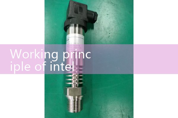
2. Key structural components 1 Starter: The core component that forces fluid to generate vortices, usually made of stainless steel material. Sensor: uses piezoelectric chips to detect pressure fluctuations and convert them into electrical signals. Shell: a Venturi tube structure that guides fluid expansion/contraction to enhance precession effects. Signal processor: integrated temperature/pressure compensation module (optional) to improve measurement accuracy.
III. Technical characteristics • Accuracy level: Conventional products can reach 1.0 level (1%) or 1.5 level (1.5%) • Range ratio: usually 10:1~30:1 • Applicable pipe diameter: DN15-DN200 (with obvious advantages for small and medium diameters) • Working pressure: Standard type 1.6MPa~4.0MPa, high-pressure type can reach 10MPa • Medium temperature: -20 ℃~+200 ℃ (special design can reach 300 ℃)
IV. Application restrictions and risk warning 1 Installation requirements: It is necessary to ensure the straight pipe section (D is the pipe diameter) from the front 10D to the back 5D to avoid flow field disturbance Medium adaptability: Not suitable for dirty media containing solid particles or fibers (prone to clogging the starter) 3 Pressure loss: Due to significant pressure loss in the throttling structure, the system energy consumption needs to be calculated Vibration sensitivity: Mechanical vibration may interfere with sensor signals and should be avoided in strong vibration environments (note: technical parameters are based on the 2024 domestic mains